Broadcast Audio Processor
Rocket Broadcaster Pro 1.4 includes the brand new Broadcast Audio Processor, designed to improve the audio quality of your streaming audio. It achieves this through a powerful signal processing chain, consisting of automatic gain control (AGC) with noise gating, multi-band compression, limiting, and loudness metering. The Broadcast Audio Processor also includes key visualizations to help you understand your audio and how it is being processed.
Table of Contents
Key Features
- Multiband peak compressor with knee
- Hybrid AGC with LUFS targeting
- BS.1770 loudness metering (LUFS)
- Peak Limiter to prevent nasty clipping and optimize audio for compression
- Easy stock presets, with preset exporting and management
- Real-time AGC scrolling waveform visualization
- Real-time compressor bands waveform visualization
- Stereo oscilloscope
- Stereo vectorscope for visualizing stereo imaging, makes it easy to identify balance issues.
- Optimized for both high DPI (retina) and standard DPI screens. Fully compatible with Windows Display Scaling.
- Resizable window with scalable visualizations.
- Low latency - Only 15ms added latency, optimized for streaming
- Signal flow VU meters
- Documentation and walkthrough video
- Supports screen scaling (high DPI / retina displays)
- Low CPU and memory usage
Quick Start
Presets
- Balanced (Default) - Provides a good overall sound for most broadcasts. Uses the AGC to hit the industry standard loudness target, while preserving the original dynamics as much possible. Minimal dynamic range compression and limiting.
- Massive Sound - Sounds similar to some heavily processed AM/FM broadcast stations. Uses the AGC to more aggressively control the loudness at the expense of dynamics, and smooths peaks with multi-band compression.
- Talk (Studio Mics) - Designed for use in a studio environment with pro-tier microphones.
- Talk (Portable Mics) - Designed for use at live events where there's higher background noise and wider variability in loudness between microphones or sources. Uses AGC aggressively to ensure all microphones are audible at sufficient volume, and squashes background noise.
- Warm and Clear - Uses multiband compression, especially in the bass bands, to add a warm signature sound to music.
- Lofi Dynamics - Uses heavy multiband compression to significantly lower the dynamics of music.
- Classical and Jazz - Uses a slower AGC to preserve the wider range of dynamics of music, suitable for classical and jazz.
- Energy Boost - Boosts presence by using heavy multiband compression on the high bands.
- Loudness Boost - Demonstrates a higher loudness target, to boost your loudness to abnormally high levels.
Visualizations
Oscilloscope
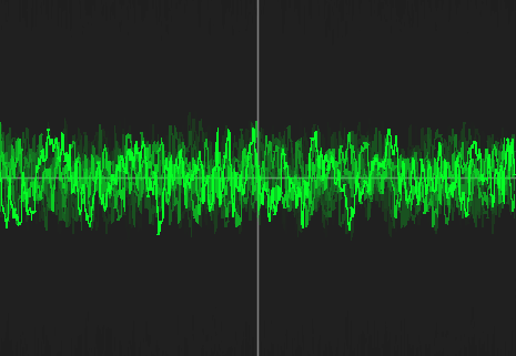
The Stereo Oscilloscope displays the waveform of the left and right channels of the master audio output, after all processing.
Stereo Vectorscope
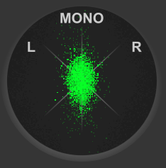
The Stereo Vectorscope allows you to easily identify problems with the stereo imaging of your audio. The master output signal is plotted in mid-side space, with left and right axes appearing at 45 degree angles.
Here's some tips on how to interpret the vectorscope:
- A balanced stereo signal will appear as a symmetric, mostly-vertical line or haze.
- A pure mono signal will appear as a vertical line, with no horizontal spread.
- A signal that is only present in the left or right channel will appear as a 45 degree line, tilted to the left or right accordingly.
VU Meters
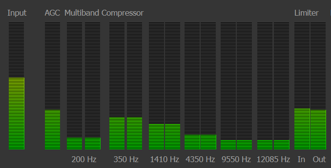
The VU meter section at the top displays the signal in decibels at various points throughout the signal processing chain:
- Input - The audio going into the broadcast processor.
- AGC - The output of the AGC.
- Multiband Compressor - Each band has a separate VU meter. The left VU is the input, and the right VU is the output.
- Limiter - The left VU displays the input of the limiter, and the right displays the output. Note that these are often different even when no limiting is taking place because there is a short lookahead.
ITU BS.1770 Loudness Meter
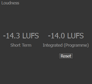

The Loudness Meter is an ITU BS.1770 and EBU R128 calibrated meter, which measures the loudness in LUFS. The BS.1770 loudness is based on a model of human hearing and better reflects how loudness is perceived compared to what is displayed on a typical VU meter (RMS). It has quickly become the industry standard for loudness.
The key useful metric is the Integrated (Programme) Loudness, which is the integrated loudness over the last hour of broadcasting. The Short Term loudness is integrated over the last 3 seconds.
The Reset Button clears the programme loudness measurement and starts it over.
The LUFS meter bar displays the Momentary loudness, which is integrated over a 400 ms window.
A programme loudness of -14 LUFS is the recommended level for streaming, and will match the loudness that Spotify and YouTube play at on most devices. If the AGC Power Target is set to -14 LUFS, the programme loudness should converge to -14 ± 0.1 slowly over 15 minutes.
AGC Waveforms

The AGC includes a scrolling waveform visualization of the input and output signal, with the input on the top and the output on the bottom.
The yellow line shows the gain of the first stage of the AGC. The orange line shows the gain of the second stage of the AGC. For more information on these, see the section on Automatic Gain Control below.
DSP Components
Automatic Gain Control
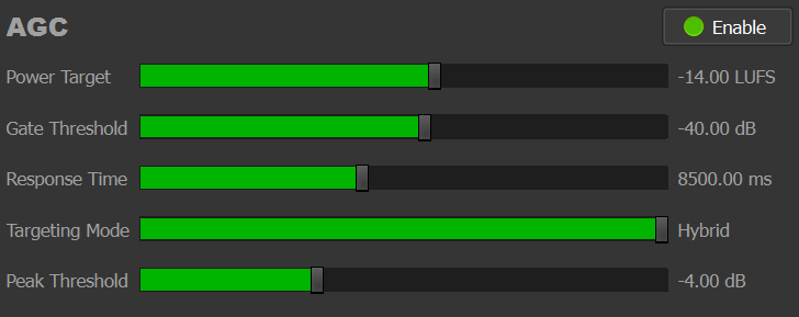
The Broadcast Processor includes a unique 2-stage hybrid Automatic Gain Control (AGC), which manages the loudness of your stream to provide a comfortable listening experience.
The AGC addresses a number of common audio quality issues:
- Insufficient input gain (audio too quiet)
- Inconsistent gain being used across different microphones
- Different program segments being at different volumes
- Improper mixing
Think of the AGC as an extra quality control step, providing extra polish to your broadcast.
Theory of Operation
The first AGC stage looks ahead to analyze the RMS of the audio, and adjusts the gain to match a target. The second stage looks back at the LUFS over the last 15 seconds, and makes a smaller adjustment to nudge the overall programme loudness to the target over longer timescales.
The AGC also implements a noise gate to squash background noise and reduce sensitivity to noise.
The first stage of the AGC also features an "accelerated" response mode, where if it is predicted to exceed the Peak Threshold, it will respond quicker to avoid overcompensating or clipping.
AGC Parameters
- Power Target: In Hybrid mode (recommended) or LUFS mode, this is the target loudness of the broadcast in LUFS. In RMS mode, this is the target average RMS.
- Gate Threshold: The threshold of the noise gate below which the gate will close and no audio will pass. The AGC will ignore signals below this threshold.
- Response Time: Controls how long the AGC takes to respond to changes in the signal's loudness. Smaller response times mean the AGC will reach much quicker, affecting the dynamics of the audio more. Longer response times will preserve the original dynamics of the audio better, but have less control over the loudness.
- Targeting Mode: Controls the mode of operation of AGC. Hybrid enables the two-stage AGC, combining short term RMS control in the first stage, and long-term LUFS loudness control in the second stage.
- Peak Threshold: Signals above this threshold trigger the AGC to accelerate its response, to prevent clipping during abrupt increases in loudness (eg. huge bass drops).
AGC Hints
- The Power Target is what the Integrated (Programme) Loudness will reach over longer timescales. On short timescales, the programme loudness is usually within +/- 1 LUFS of the target, and over longer timescales it will converge to +/- 0.1 LUFS.
- If you're hearing many sharp drops in loudness or seeing sharp drops in the yellow line (1st stage) on the scrolling waveform, try increasing the Peak Threshold parameter.
- If you increase the Power Target, you may need to increase the Peak Threshold too.
Multiband Compressor

The Multiband Compressor reduces the dynamic range of your audio by reducing the volume of loud parts, and applying a gain to boost the volume of quiet parts. This has the benefit of reducing harsh peaks, preventing clipping, and making your stream more comfortable to listen to. On vocals, it can reduce sharp sibilance and act as a de-esser.
Compression is applied over 6 separate bands in order to independently shape the different dynamics across each band without affecting the others. This approach greatly improves listening comfort and adds a level of polish to your broadcast.
The compressor on each band has the following parameters:
- Threshold - Signals above this threshold (in dB) will be reduced by the ratio.
- Ratio - How much to reduce the gain of a signal by.
- Attack - How quickly to react to signals above the threshold and start applying compression.
- Release - How quickly to reduce the compression once the signal falls below the threshold.
- Makeup Gain - A fixed amount of gain applied after compression. Since compression reduces the gain and dynamic range of signals over the threshold, the makeup gain can help bring the level back up.
- Knee Width - The range around the Threshold where the compressor will smoothly apply the gain reduction. The higher the Knee Width, the softer than transition into compression will be.
Each compressor band includes a scrolling waveform visualization, to help show the effect of compression. A small white horizontal line also shows the current amount of gain reduction on a scale of 0 to -36 dB.
Limiter

The final stage of the Broadcast Processor is a Peak Limiter, which performs hard limiting in order to prevent distortion before your audio is encoded for streaming.
The Limiter has the following parameters:
- Threshold - The peak threshold (dB) above which the gain should be aggressively reduced in order to prevent clipping.
- Response Time - How quickly to react to peaks above the threshold
- Makeup Gain - A fixed gain to apply to the audio.